Sunday 20 March 2016

Micropython Pyboard V1.0

As always this is for entertainment only, well it's to stop me going mad as well.

I started this post a month or two ago but life got in the way and it didn't get finished so I've finally got the time to get back to it, I have been working on a few projects but I had to tell you about a recent find of mine with the development boards that I have become obsessed about. So lets go;


I took delivery of one of these PyBoards V1.0 the other day and was totally won over by the product, so what is a Micropython PyBoard V1.0 and what can it do or more to the point what can't it do and it's biggest limitation is your imagination or at least it's mine, you will be a very bright person with a million ideas for it. On the Micropython site it describes it as;
"The pyboard is a compact and powerful electronics development board that runs Micropython. It connects to your PC over USB, giving you a USB flash drive to save your Python scripts, and a serial Python prompt (a REPL) for instant programming. Requires a micro USB cable. Works with Windows, Mac and Linux."
They are right, it works with any OS and the Micropython OS that it operates on is fantastic, I am still in the early stages of learning it and what the board is capable of but wow, it's a fantastic little board, cheap and easy to use.


 Micropython Board V1.0

 It's a small board but it has amazing features


Left is the USB Connector, Right is the Micro SD Card Slot

As you can see from the images the board is small but it packs some great features and is well worth looking at and using in some of your projects, search it on Google and or eBay and you will find all the info you would ever need on it. I got mine from Core Electronics in Australia but they would be available most places that sell Arduino, Raspberry Pi's and the like.

The next on the list of projects were my Electronic Kits, I have been building Kits from Dick Smith's, (Now Gone) Jaycar, Altronics and Heath kits and I have a love of time, watches, clocks and some new Kit Clocks from Banggood in China, they were cheap BUT excellent quality with some good fun features like alarms, chimes and temperature.
One of the clock kits was mostly surface mount and it really tested my ageing eyes and shaky hands but I got it working after some extra soldering and repair work but it taught me a lot and I love the finish product. Actually I enjoyed it so much that I have ordered two more Clock kits. The dearest kit was $18.9AUD delivered and all the others were under $10.00AUD plus delivery and they are a mixture of SMD and through hole components. I now have a soldering iron better suited to SMD components and I have learnt some new tricks to hold and place components before soldering that makes the job easier and more professional looking so they should be easier and more fun to build. My love of clocks and time is now married to my love of kit building and I end up with very handy time pieces to add to my collection.


This on Stands 41mm high with 33mm digits


All Through Hole Components

The above clock displays Time naturally, Date, Temperature (Adjustable), and Day of the week but as a number, ie. 1 through 7. it has a backup battery and the instructions were brilliant and as you can see it's mounted in a plastic box so your handy work is visible, great looking bit of kit and Very Easy to build. Bit of learning re adjustments but you will master it after 2 or 3 goes, well it took me that many goes anyway, you young ones will master it in 1.


 The second Clock, components not a visible thankfully


The digits are 25mm tall and you can select different Fonts

The above clock was the Surface Mount Components clock and it wasn't as easy to put together and I had to do a bit of tidying up and re soldering but it taught me a lot about working with SMD components and I now feel very confident that I will do my nest clocks, all SMD, much better and they will look much neater when finished, the components will be very visible in them so they better look much neater. This clock tells the time naturally, day of the week, ie. Mon etc, Date in the format Month/Day, Temperature (adjustable) but affected by the heat generated in the IC's, plus it has alarms and chimes. The instructions are in Chinglish and very hard to decipher, you need to be able to read a schematic and ID components very well to be able to build this kit but when finished looks great and works well, it also has backup battery and took me a few goes to get the adjustments sorted but I was well pleased with the finished components.

I am looking forward to building the two new kits when they arrive from China, Banggood is a great company to deal with, excellent products but be careful what you buy as some of it is very cheap but for the most part I have been very pleased with the finished product. The thing I like is the options they give you with delivery, yes it costs more but if you spend a bit of money you can insure it etc which is great in my books, They also have great follow up and refund when they can't supply the components, they have great contact procedures and do exactly what they say they will do. they get a 10/10 score from me. Mind you I don't buy big ticket items from them, I deal locally for 99% of my big ticket items, mostly from Core Electronics, Wiltronics, Jaycar and Altronics as they are the best hobby suppliers in Australia in my book and Element14 are the best pro supplier I deal with but not the only one's, I do have other suppliers but don't deal with them as often as I do with the others, eBay is often visited and purchased from as well.

Anyway, enjoy your hobby, build a few kits, it's greet fun and you will learn lots as you go, it also hones your soldering skills and you end up with a very handy unit, test tool or just fun product at the end of it. If it doesn't work first go, you also learn diagnostic skills as you get it going, what better way to learn than by doing. 73's and have fun.
TJ. VK2MTJ

Tuesday 24 November 2015

PopPet The Robot V2 Bluetooth

PopPet the Robot by Edwards Robotics

As always this is for entertainment and to help stop me going mad.

This Post was Written and Edited on my pcDuino running Ubuntu 14.04.

I updated it on Friday 27/11/2015 about the Bluetooth Operation.

Some eight months ago I ordered a robot from Edwards Robotics that was fully funded by Kickstarter and was in the final stages of being prepared for delivery to the people who funded the project first, then people like me who purchased via the PopPet The Robot site would be next on the list of deliveries and true to my form I started to get worried that I had been played for a fool and had lost my $120.00, so I sent off a not so pleasant email which got a very nice reply and an offer was made to refund me or wait just a little longer and the Kit for the Robot would soon be packaged and sent out. I agreed to wait and in the reply he said that he would add something extra for the long wait, I thought well okay at least he is trying to make up for the extra wait, to my surprise it arrived the other day, only a week or so after his reply and true to his word I did in fact get a little extra, actually I got a Huge Amount Extra, he sent me the V2 Bluetooth version and it is amazing, for $120.00 (not sure what the current price is) it is excellent value for money, it meets and exceeds all my expectations and after a few initial hiccups I got it working and it does everything the instructions say it will do, I have not at this point in time (24/11/2015) set up the Bluetooth operation but by the time this goes to print I hope to have it setup and tested. So let me show you the product and give you an honest appraisal of PopPet The Robot V2 Bluetooth as it was delivered to me in Kit Form. This is for this kit only and does not mean all kits will be sent out like this one.

PopPet V2.0 Bluetooth by Edwards Robotics
The complete instructions can be viewed on line at www.poppettherobot.com as can all the detailed information, even the files for making the chassis components at home or at least they were. The sketches required to set up the sensors and the final sketches required to get PopPet up and running are there for you as well, all of it is Open Source and is Arduino Compatible. 


  PopPet's Box

As noted above the kit doesn't have any paperwork in it because it is all available from the PopPet Home Page listed above and is very easy to locate and read, the layout and information is excellent and if you follow them step by step you will get a robot up and running with a minimum of fuss.

The kit is normally complete and all the components required to assemble are included in the kit, my kit however was missing the bag of nuts, screws and or fasteners BUT this wasn't a problem for me as I have an extensive number of fasteners here so I was able to continue without delay. 


PopPet Unpacked 

The laser cut components look fantastic an the initial inspection was very promising and they fitted together perfectly and all other components were in the kit. I was extremely pleased with the length of the USB cable, it meant that I could have it sitting in front of me while connected to the computer, I hate the short leads that normally come with the Arduino Clones out there. Okay the next step for me was to look at all the steps in the construction process to make sure that I had a good idea of what was to come and made a note of any special steps  so that I could pre-empt them as I went through the build.

  PopPet out of the Bags

One of the things that gives me the s#!^s is a project that doesn't follow a set wiring colour code and I was very pleased with the wiring information given in the instructions, the wiring diagram was excellent, I printed it out and made sure that I got it right first time so that I wouldn't damage the electronic components, mind you they are a bit forgiving but can still be easily damaged take care to read and follow it carefully.
Now to the electronic components, I always have a very close look for electrical problems, after 42 years as an automotive electrician I know how easy it is to overlook even the basic things so I very carefully inspect all components, lucky I did in this instance, the Brain as it is called on the PopPet site was not up to my standard, the soldering left a lot to be desired, some of the through hole components or pins actually were so badly soldered I could see light through them, I think it would have worked but for how long was my worry, this didn't present a big problem to me as I am very experienced at component level repairs and soldering and I set about re-soldering all the suspect joints, a good clean first and the solder applied as required and all worked perfectly.

PopPet's Brain (Dagu Arduino Mini Driver Board Clone?)

PopPet's Brain is an Arduino Compatible Two Motor full H Bridge Mini Controller that makes the whole thing so easy to build, program and wire up and the size is perfect for this style of project, in general it was nicely made except for the above mentioned aspect but that aside is was perfect for the job. 

As I mentioned I was upgraded to the V2 Bluetooth Kit and the Bluetooth is the normal fully self contained unit that simply plugs into the Mini Driver Board on the inline header pins at the center of the board just in front of the main IC at the USB connector end, BUT don't plug it in untill you have downloaded the Sketch to the brain otherwise you will have problems with programming.

 The Bluetooth Module

The construction is made very easy by the use of laser cut MDF that looks great as a result of the burnt look, once finished it really is a great looking robot. The mounting of the motors is easy as is the construction of the wheels also made of three sections of MDF and a rubber "O" ring for the tyre that is simply screwed together. I have used the same construction method in a few of my robots as well, just so simple. You can see the wheels in the third image in this post.

 The HC-SR04 Ultrasonic sensor


 The IR Sensor


The Piezo Buzzer

The use of standard Arduino Shields makes the robot easy to build, wire up and write a sketch to suite because of the Libraries that are available, the number out there never ceases to amaze me and the general quality is fantastic to say the least. I did run into another problem during construction and that was with the battery holder, it had an open circuit in the earth or negative wire, the crimp wasn't done correctly but was very easy to find and repair so no real problem but had me guessing for a second or two.

 The IR Sensor and Piezo Buzzer on the base Plate


 The Battery support and center Plate fitted

Note in the image above that the wiring is routed through gaps in the center plate and are positioned to make it easy to connect all the components together. The lower plate in the above image is the battery support, the Motors at the front supply the other support, simple solution to mount the battery box in a small space, well done.


The Sound Holes on Left and IR Sensor on Right

The above image shows the sound holes, left and IR sensor slots, far right but it also gives access to the adjustment trim pot for the sensor, this is done for all the sensors that need to be adjusted and makes it so easy to set it all up, some very good solutions included in the design to make it very easy to build. You can also see the mini ball castor on the far left, make sure you don't over-tighten the mounting screws as it can deform and stop the ball rotation, I know because it happened to me and my heavy hand. One little thing to note in my construction is that I didn't use screws and nuts to hold the wheels together, have a look at the finished product images at the end, I used Roll Pins, made of metal and because of the spring loading as you insert them they hold the wheels together very well but I would use what is supplied in the kit for normal construction, I only used them because I had some here to spare and they were the perfect size.

The little DC Motor mounted low in the chassis

I have to say that the overall design is excellent, it is obvious that the extra time taken to deliver the kit was taken up in design improvements and V2.0 really is a great product.

 PopPet's Face, cheeky little thing

Two of the setup sketches didn't compile in my version of the Arduino IDE, I have the very latest version and it makes note of the fact that the sketches are better suited to an older version of the IDE so I did the tests and setup on my Banana Pi with Ubuntu and the older version of the Arduino IDE in it which worked perfectly, mind you I did do the final program or Sketch Upload on the Windows Laptop and it worked perfectly from that as well so do some sketch work to learn how to write a sketch, that is the best way for me, use the many sketches out there and make them work for my project, great fun when you achieve what you want then share it with the community when you finish.

The kit as sent to me was lacking in finish quality and some parts but that didn't worry me greatly as I had enough parts to complete the build and the build quality of the brain was a little less than perfect but once again it most likely would have worked but for how long was anyone's guess but once again it wasn't a problem for me as I enjoy the challenge of the build. Also the fact that two of the setup sketches didn't compile wasn't a problem as it gave me another challenge as well, because it made me think about why they wouldn't work and that in itself taught me a lot about sketches, BUT and there is always a but, if someone else got this kit it would have been a problem, especially if they were new to Arduino, robotics and electronics so for that reason I'm giving this kit 6 out of 10, if all the components were in the kit and it had no other concerns it would have deserved 9.5 out of 10 at least and when you consider that it is a young Australian who designed and built the kit from scratch and is marketing it to the world he is destined for great things and I give him a perfect score, 10 out of 10. A job very well done and a lot of fun building, debugging and testing my PopPet the Robot.
If your into Arduino, Robots and Electronics then you must get yourself a PopPet.


The ON, OFF switch

Now that I have had PopPet running for a while I did find the switch setup a bit of a problem in that the robot kept hitting it and turning itself OFF, not a big problem but one that I will overcome by making a small shield for it so it doesn't happen. The sensors work well and I love the fact that it turns off if my grandson picks it up, he likes to play with the wheels as they turn, now all I need to do is stop him from wanting to push it. I did a short video and took a few images of it finished and as I said before you must get yourself one of these robots, it is a great little project.

Update; 27/11/2015.........

I did a test on the Bluetooth Operation of PopPet which was easy to set up and get going. I uploaded the Bluetooth Sketch to PopPet and then fitted the Bluetooth Shield to the Mini Board, I loaded the app to my Android Tablet, one of those cheap Pendo units that I purchased some months ago for use with my Arduino's and the like and it took two attempts to pair them but once it did it all worked very well for about five minutes and then it locked up, you could hear the motors trying to go all the time but that was all. Not a big problem as all I had to do was restart the app and away PopPet went. The different modes and the way it talks is excellent and they all worked very well, the dot that works like a joystick was about the best in my books but the explorer mode was excellent as well, the grandkids will love it when they come over on the weekend.
So the final verdict is 9 out of 10, a very well thought out robot kit that will give everyone from the youngest to oldest robot builders out there a lot of fun building and using and more to the point modifying the sketches to get it to do other things or just developing your own, however you do it it will be a lot of fun.  


The Short Video


Tuesday 8 September 2015

Tamiya Track & Wheel Robot V1

This is for entertainment only but it worked perfectly for me.
I had a Tamiya twin motor and gearbox kit that I wanted to use in a robot but I wasn't sure what type of robot to build until I came across the Tamiya Track & Wheel Set in Kit form, problem solved.
I got it on eBay, actually I got two kits as they looked like an excellent kit and I wasn't wrong, they are an excellent kit that can be configured in a number of ways to suite the design that you might have.

                                        Tamiya Track & Wheel Set


                                The Kit comes with excellent Instructions

The only thing you need to do is work out what setup you want and then put it together, the track comes in different lengths so you can make up the correct length overall and it is very simple to put it together. I wanted the typical tank setup and I even had some track left over so I could have made it longer if I wanted to. 


                        This is the setup I settled on but it will do many more


                               The Twin Motor and Gearbox Kit Mounted

The components are held together by plastic two part rivets and they are the only things I used in this build, I wanted to test them and they seem to be holding well enough at this stage but I'm not totally convinced that they will hold if the robot gets a lot of use by the grand kids so it might get a few screws and nuts to make it kid proof, well okay sort of kid proof.
You can see that the motor has the usual capacitor setup to help protect the motor H Bridge controller and the gearbox is mounted with the two part rivets as well, lets see how they hold. 
The capacitors are 0.1uF and one goes across both motor power leads and then one from each supply lead to the motor case, this is very important if you want the controller to last.

                            The capacitors across the motor power leads


                                           The Arduino UNO Clone

As with most of my Rolling Robots I use an Arduino of one type or another and I used the UNO here because I have a number of DK Electronics Motor Controller Shields that I purchased some time ago as they were so cheap in lots of ten. They use the L293D H Bridge DIL IC's and a SN74HC595N DIL IC interface on the shield and simply plugs into the UNO and makes it very easy to control up to 4 DC motors or 2 stepper motors so it gives you a few options to power your robot. The number of sketches available for this shield are to many to mention but you will have no problem getting one to suite, I will include the sketch I used here.

                           The Arduino UNO with connectors to the front

                                 The Adafruit Motor Controller Clone V1


As you can see in the image above the controller simply plugs into the UNO and the motor and power leads screw into the headers on the shield, it also has connectors for 2 servos and you can add pins for A0 to A5 as required and it also has 5V and 0V connection points as well, in all a very handy shield, it is no longer made by Adafruit but they have a updated version now that has better specs but clones are still available of the first version, check eBay.


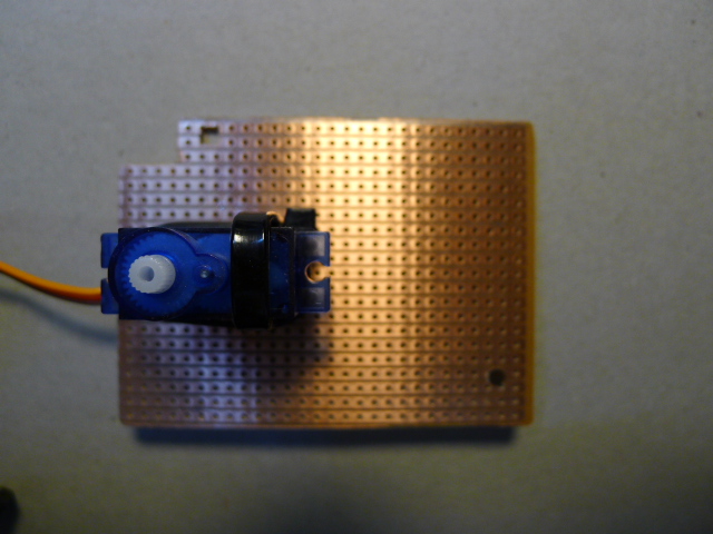
                   The Servo Mounting Plate made from PCB Vero Board


                                    I used Cable Ties to mount the Servo


                                  The second Cable Tie to Hold the Servo


The images above show the PCB Vero Board and Cable Ties used to mount the servo to the robot, I used the UNO footprint to cut the board to size and locate the mounting holes and put holes in the board for the main cable tie and used the second smaller cable tie to stop it sliding forward or backward and it works very well.


                      The Ultrasonic Sensor mounted to a Bracket and Servo


                        The Ultrasonic Sensor is held on with Fishing Line


The Images above show the sensor and bracket mounted to the servo, the plastic bracket has small holes that line up with the mounting holes in the sensor PCB and I used fishing line to hold it together. The bracket is screwed to one of the servo horns but you need to cut the excess length of the screws off so they don't foul on the servo. If you look closely at the top image you will notice cutouts in the board to allow the wiring to be connect to the shield pins and the wiring for the motors is under the servo board to keep it safe. I used a battery box that had a switch in it to simplify the construction process and it works very well, I have used this set up before and it keeps things simple.
I was worried about the height of the servo and sensor but it worked beautifully on the first test and avoided obstacles very well so I will keep it as is.


            The Battery Box is mounted on the Motor with Hook & Loop Tape


                           The Switch can be seen on the Front of the Box

If you look at the above images you can just see the Switch on the front right corner of the battery box and this makes the construction of the robot very simple, it also keeps the wiring easier to manage as well.
You can also see the white plastic threaded standoffs that I used to mount the Arduino UNO and shield as well as the servo board to the chassis, the screw and standoff are plastic so they won't interfere with the PCB's circuits and you can get three different lengths of nuts so you can configure the layout to best suite the robot you are building and length of standoff required. You can get these components from Jaycar in Australia. 

                                       The Video of the Maiden Voyage

As you can see the sketch needs a bit more work but on the whole it works reasonably well, the speed and turning to avoid obstacles is good so with a little bit of work you should be able to get the sketch work well with your version of this robot should you decide to build one. The motor shield will work with most DC motors and if you read the information in the sketch you will be able to work out how to wire the robot, very simple actually, anyway here is the sketch in it's basic form, you will need to tweak it to suite your setup, have fun.

Just copy and paste this into your Arduino IDE and away you go, it will need work, this is a text document and the lines have word wrapped to the next line so sort that out first then compile it to make sure you have it working.


#include <AFMotor.h>
#include <Servo.h> 
#include <NewPing.h>

#define TRIG_PIN A4 // Pin A4 on the Motor Drive Shield soldered to the ultrasonic sensor
#define ECHO_PIN A5 // Pin A5 on the Motor Drive Shield soldered to the ultrasonic sensor
#define MAX_DISTANCE 200 // sets maximum useable sensor measuring distance to 200cm
#define MAX_SPEED 240 // sets speed of DC traction motors to 180/256 or about 50% of full speed - to get power drain down.
#define MAX_SPEED_OFFSET 15 // this sets offset to allow for differences between the two DC traction motors ****** from 20
#define COLL_DIST 60 // sets distance at which robot stops and reverses to 10cm
#define TURN_DIST COLL_DIST+10 // sets distance at which robot veers away from object (not reverse) to 20cm (10+10)
NewPing sonar(TRIG_PIN, ECHO_PIN, MAX_DISTANCE); // sets up sensor library to use the correct pins to measure distance.

AF_DCMotor motor1(1, MOTOR12_2KHZ); // create motor #1 using M1 output on Motor Drive Shield, set to 1kHz PWM frequency
AF_DCMotor motor2(2, MOTOR12_2KHZ); // create motor #2, using M2 output, set to 1kHz PWM frequency
AF_DCMotor motor3(3, MOTOR12_2KHZ);
AF_DCMotor motor4(4, MOTOR12_2KHZ);
Servo myservo;  // create servo object to control a servo 

int leftDistance, rightDistance; //distances on either side
int curDist = 0;
String motorSet = "";
int speedSet = 0;

//-------------------------------------------- SETUP LOOP ----------------------------------------------------------------------------
void setup() {
  myservo.attach(9);  // attaches the servo on pin 9 (SERVO_2 on the Motor Drive Shield to the servo object 
  myservo.write(90); // tells the servo to position at 90-degrees ie. facing forward.
  delay(750); // delay for one seconds
 }
//------------------------------------------------------------------------------------------------------------------------------------

//---------------------------------------------MAIN LOOP ------------------------------------------------------------------------------
void loop() {
  myservo.write(90);  // move eyes forward
  delay(90);
  curDist = readPing();   // read distance
  if (curDist < COLL_DIST) {changePath();}  // if forward is blocked change direction
  moveForward();  // move forward for 1/2 second
  delay(350);
 }
//-------------------------------------------------------------------------------------------------------------------------------------

void changePath() {
  moveStop();   // stop forward movement
  myservo.write(36);  // check distance to the right
    delay(500);
    rightDistance = readPing(); //set right distance
    delay(500);
    myservo.write(144);  // check distace to the left
    delay(700);
    leftDistance = readPing(); //set left distance
    delay(500);
    myservo.write(90); //return to center
    delay(100);
    compareDistance();
  }

  
void compareDistance()   // find the longest distance
{
  if (leftDistance>rightDistance) //if left is less obstructed 
  {
    turnLeft();
  }
  else if (rightDistance>leftDistance) //if right is less obstructed
  {
    turnRight();
  }
   else //if they are equally obstructed
  {
    turnAround();
  }
}


//-------------------------------------------------------------------------------------------------------------------------------------

int readPing() { // read the ultrasonic sensor distance
  delay(50);   
  unsigned int uS = sonar.ping();
  int cm = uS/US_ROUNDTRIP_CM;
  return cm;
}
//-------------------------------------------------------------------------------------------------------------------------------------
void moveStop() {motor1.run(RELEASE); motor2.run(RELEASE); motor3.run(RELEASE); motor4.run(RELEASE); }  // stop the motors.
//-------------------------------------------------------------------------------------------------------------------------------------
void moveForward() {
    motorSet = "FORWARD";
    motor1.run(FORWARD);      // turn it on going forward
    motor2.run(FORWARD);      // turn it on going forward
    motor3.run(FORWARD);
    motor4.run(FORWARD);
  for (speedSet = 0; speedSet < MAX_SPEED; speedSet +=2) // slowly bring the speed up to avoid loading down the batteries too quickly
  {
    motor1.setSpeed(speedSet);
    motor2.setSpeed(speedSet+MAX_SPEED_OFFSET);
    motor3.setSpeed(speedSet);
    motor4.setSpeed(speedSet+MAX_SPEED_OFFSET);
    delay(5);
  }
}
//-------------------------------------------------------------------------------------------------------------------------------------
void moveBackward() {
    motorSet = "BACKWARD";
    motor1.run(BACKWARD);      // turn it on going forward
    motor2.run(BACKWARD);     // turn it on going forward
    motor3.run(BACKWARD);
    motor4.run(BACKWARD);
  for (speedSet = 0; speedSet < MAX_SPEED; speedSet +=2) // slowly bring the speed up to avoid loading down the batteries too quickly
  {
    motor1.setSpeed(speedSet);
    motor2.setSpeed(speedSet+MAX_SPEED_OFFSET);
    motor3.setSpeed(speedSet);
    motor4.setSpeed(speedSet+MAX_SPEED_OFFSET);
    delay(5);
  }
}  
//-------------------------------------------------------------------------------------------------------------------------------------
void turnRight() {
  motorSet = "RIGHT";
  motor1.run(FORWARD);      // turn motor 1 forward
  motor2.run(BACKWARD);     // turn motor 2 backward
  motor3.run(BACKWARD);
  motor4.run(FORWARD);
  delay(300); // run motors this way for 400ms
  motorSet = "FORWARD";
  motor1.run(FORWARD);      // set both motors back to forward
  motor2.run(FORWARD);
  motor3.run(FORWARD);
  motor4.run(FORWARD);
}  
//-------------------------------------------------------------------------------------------------------------------------------------
void turnLeft() {
  motorSet = "LEFT";
  motor1.run(BACKWARD);     // turn motor 1 backward
  motor2.run(FORWARD);      // turn motor 2 forward
  motor3.run(FORWARD);
  motor4.run(BACKWARD);
  delay(600); // run motors this way for 400ms
  motorSet = "FORWARD";
  motor1.run(FORWARD);      // turn it on going forward
  motor2.run(FORWARD);      // turn it on going forward
  motor3.run(FORWARD);
  motor4.run(FORWARD);
}  
//-------------------------------------------------------------------------------------------------------------------------------------
void turnAround() {
  motorSet = "RIGHT";
  motor1.run(FORWARD);      // turn motor 1 forward
  motor2.run(BACKWARD);     // turn motor 2 backward
  motor3.run(BACKWARD);
  motor4.run(FORWARD);
  delay(600); // run motors this way for 800ms
  motorSet = "FORWARD";
  motor1.run(FORWARD);      // set both motors back to forward
  motor2.run(FORWARD); 
  motor3.run(FORWARD);
  motor4.run(FORWARD);
}

Have Fun,
Cheers, Terry VK2FDGN


Wednesday 19 August 2015

VK2FDGN

I am now on air with my new call sign of VK2FDGN and I am on HF, VHF and UHF governed by the Foundation Licence 10 Watt max but I am normally on the Bindo Repeater for 2M, 3575 on 80M and the national call frequency on UHF.
I have been very busy setting up the Radio Shack and haven't had time to build any other projects but more to come and now I hope to do some for Amateur Radio.
I competed in the Amateur Radio Remembrance Day Competition with the Amateur Radio Central West Group, VK2ACW on the weekend of 15/16 August and we had a fantastic time. We made over 260 contacts over the 24 hour period which wasn't bad given two of us were newbies and I had only had my licence for two weeks so I had a lot to learn. This may have earned us a 3rd place if the count is correct, will have wait for the official results to be sure.
Anyway more projects to come soon.
73's. VK2FDGN.

Saturday 11 July 2015

Amateur Radio Foundation Licence, VK2F###

Well I did it, I passed all the Exams for my Amateur Radio Foundation Licence and I will have my own Call Sign very soon, it will be a VK2F### and I will be limited to 10W,Px and on 80 Metres, 40 Metres, 15 Metres, 10 Metres, 2 Metres and 70 Centimetres but it means that I will be on the air and I will be able to upgrade to my Standard and then Advanced certificates as time permits, the satellites that I am interested in will be easier to receive with the correct equipment that I will be able to use so it should open up a new world of Arduino projects for me to play with.

Friday 26 June 2015

RTL.SDR 30MHz to 3GHZ Ultra-Wideband Home Made BI-CONICAL ANTENNA

Yes I did write 30MHz to 3GHz and yes I have built it and tested it and it surprised me but to test it across the full 30 to 3 really is out of my league but it made a huge difference to the number and strength of signals that I was receiving. This is my version of a design I found on YouTube at;
https://www.youtube.com/watch?v=xhW4QQruBTo
I didn't have the money to get the aluminium sheet at $105.00AUD each (at Masters) and I needed two so I came up with the next best thing, a roll of Hardaz Vermin Wire Mesh 6.5X6.5mm, 15cmx10M roll for about $20.00AUD. It wasn't wide enough so I modified it by soldering two lengths together and it almost came out at the correct size, so close it didn't matter to me anyway. Now to make a CONE is a bit tricky and it took me a few goes with big sheets of paper first but it worked okay in the end, mind you it isn't pretty but it tests perfectly electrically and works very well.

                   It looks a bit like an hourglass - Bi-Conical Antenna V1


                             The centre spacer is a plumbing pipe joiner

The top and bottom formers are 10mm MDF and the three supports are good quality dowel, I also cut out some curved MDF to hold the wire in the centre and as circular as possible, you can just see one of them to the right of the centre dowel on the bottom former. All the dimensions are in the video for the wire and you will need to design your own support frame. As I said it isn't perfect, even a bit wonky but it works very well. The RTL.SDR comes with a Small antenna and simply didn't work at all in my location so I made up a 2M coaxial co liner dipole with three elements and it works fantastically on the amateur band but not much good above and below that. The bi-conical was picking up hundreds of automotive RF remote door lock transmitters on my first try, amazing to listen to, yes I'm nuts I know, also I was listening to aircraft coming and going from Sydney airport and I live in Bathurst, on a big hill and I look towards Sydney from my yard and I couldn't do that on the original antenna or the coaxial antenna so if you want to build a cheap antenna that works amazingly this is the one for you. By the way get it up as high as possible and it will blow you away I'm sure, it did me.
PS. I forgot to mention that I got the RTL.SDR so I could receive and play with the Cubesat, Amsat and othersat's out there so I will be building a yargi or two to get good signals for them and most of the sensors have arrived for the Arduino home based sat so more on that later as well.

Saturday 30 May 2015

ArduSat; Arduino in Space.

Well I don't know about you but I love Electronics, Arduino, TI LaunchPad, Freescale FRDM Platform and every other development board out there and I get up to 10 e-mails a day from all the popular electronic stores and the like and I got one the other day and I was instantly hooked. It was about Arduinos and Space, NASA's Curiosity Rover team member Luke Dubord and our very own Jonathan Oxer from "Freetronics", it was Freetronics that sent the e-mail and I use a bit of his gear in my robotics development etc. All of my robots use the Arduino Platform, I have a few genuine boards and a lot of clones but it is all Arduino based. I have ordered all of the components and I will be playing with them in a very low orbit, ie my computer room, but you must check it out,
https://www.ardusat.com and also check out;
 www.youtube.com/watch?v=0GHMTXiDqoA
and another one to look at is;
www.edn.com/electronics-blogs/esc/4439386/13-engineering-truths-proved-by-NASA-s-Curiosity-Rover
This should be the link to the e-mail online;
http://us6.campaign-archive2.com/?u=6c6eae339297e03e05631429d&id=6fe06ca8b0&e=106891729c
just copy and paste it into your browser, it worked perfectly for me.

The sensors that you will need include a Luminosity Sensor, Temperature Sensor, Accelerometer, Gyroscope, Magnetometer, Ultraviolet Light Sensor and Infrared Thermopile but one of them is a 10DOF IMU Sensor Module that has a number of the sensors built into it, I got mine from Core Electronics in Australia on eBay for $24.00AUD but they are available on eBay from China for a lot less, I like to shop at home as much as I can.

The Ardusat site has most of the information required and links to github for the Arduino libraries etc needed for all of the sensors and example sketches to test them and away you go, some of the best education information that I have found on the Internet from anywhere in the world about electronics and Arduino, it's a must.

Cheers, Terry.